Blog
A Brief Introduction To Filter Circuits
25 May 2024
In the rectifier filter circuit, there are two parts of the circuit altogether, respectively the rectifier circuit and the filter circuit, the functions of the two are different, the function of the rectifier circuit is to convert the sine wave AC voltage, and the function of the filter circuit is to convert the unidirectional ripple voltage, and the functions of the two parts of the circuit work together to fully complete the conversion of AC voltage, and further improve the stability of the output voltage.
After the AC is rectified, the pulsating DC power supply cannot be directly used as the power supply of the electronic circuit due to the large AC ripple it contains. This AC ripple component can be greatly reduced by the filter circuit, so that the rectified voltage waveform becomes relatively smooth.


1、Capacitor filter circuit
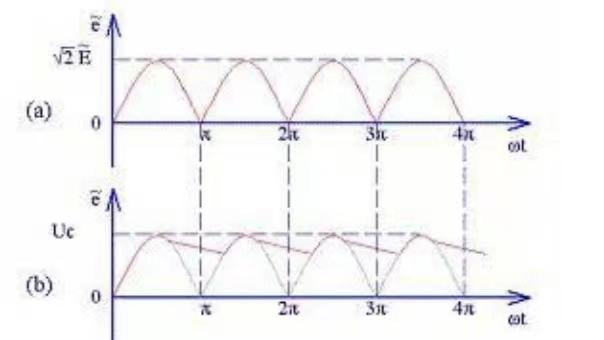
See Figure 1 for the capacitor filter circuit diagram, the capacitor filter circuit uses the charge and discharge principle of the capacitor to achieve the role of filtering. In the rising section of the pulsating DC waveform, the capacitor C1 is charged, and the charging speed is very fast because the charging time constant is small; In the descending section of the pulsating DC waveform, the capacitor C1 discharges, and
the discharge speed is very slow due to the large discharge time constant. Charging starts again when C1 is not fully discharged. In this way, the filtering effect is achieved by repeated charging and discharging of the capacitor C1. The voltage waveforms at both ends of the filter capacitor C1 are shown in Figure 2(b).

Advantages: The capacitive filter circuit has little ripple.
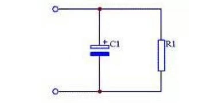


Figure 1: Capacitor filter circuit


Figure 2: Capacitor filter circuit


2、Inductance filter circuit
The inductance filter circuit diagram is shown in Figure 3, the inductance filter circuit is to use the inductor to the reverse electromotive force of the pulsating DC to achieve the effect of filtering, the larger the inductance, the better the filtering effect.

Advantages: The inductor filter circuit has a good load capacity, and is mostly used in occasions with large load current.
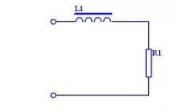

Figure 4: LC filter circuit diagram


Are you looking for more information about EverExceed's  professional products and solutions?  Our expert team is always here to help. Please fill in the form and our sales representative will contact you shortly. EverExceed | Empower, Energize, Exceed the Energy you Expect forever.
copyright © 2024 EverExceed Industrial Co., Ltd.all rights reserved.
leave a message
welcome to everexceed
If you are interested in our products and want to know more details,please leave a message here,we will reply you as soon as we can.

home

products

about

contact